


M-series Virtual IO Module 2
The DeltaV™ M-series Virtual I/O Module 2 (VIM2) provides nonintrusive simulation of the DeltaV M-series I/O Cards and digital bus field devices for process simulation when used with Emerson’s Mimic Simulation Software. DeltaV control strategies and system configurations can be fully tested with this powerful simulation interface.
分类:
Emerson
关键词:

咨询热线:
产品描述
Introduction
The DeltaV™ M-series Virtual I/O Module 2 (VIM2) provides nonintrusive simulation of the DeltaV M-series I/O Cards and digital bus field devices for process simulation when used with Emerson’s Mimic Simulation Software. DeltaV control strategies and system configurations can be fully tested with this powerful simulation interface.
The VIM2 also provides an interface to Ethernet I/O networks and devices that use e.g. the Modbus TCP or EtherNet/IP protocol drivers. DeltaV M-series controllers can read and write signals from plant floor devices connected to Ethernet I/O networks such as PLC’s, motor control centers,and weigh scales.
Benefits
Non-Intrusive DeltaV I/O simulation. Use the VIM2 in conjunction with Emerson’s Mimic Simulation Software to simulate your DeltaV M-series I/O and digital bus field devices.
• Supports DeltaV I/O modules. Provides completely non-intrusive simulation of all DeltaV M-series I/O Modules. Supports autosensing of I/O and accurate testing of controller loading. DeltaV configuration can be fully tested without modifying the control strategies.
• Digital bus support. Provides simulation of all DeltaV digital busses and Foundation Fieldbus function blocks. Supports FOUNDATION Fieldbus control in the field configuration testing.
• Powerful simulation solution. Provides full simulation of up to 64 DeltaV I/O modules per controller. Simulation execution is fast and efficient; the DeltaV controller thinks it’s talking with real IO.
Powerful integration solution. Use the VIM2 in conjunction with the Ethernet I/O drivers to integrate your DeltaV system with your Ethernet I/O device networks.
• Large device capacity. Each VIM2 emulates four DeltaV Serial Cards and support up to 128 Serial Card Datasets of information from up to 128 network devices in simplex and up to 256 in dual simplex installations as well 16 devices in redundant installations. Communication over the Ethernet I/O device network is fast and efficient.
• Flexible networking. User configurable IP addressing allows the VIM2 to be used in almost any plant environment regardless of networking scheme. The VIM2 and the Ethernet I/O devices must be on the same IP subnet to communicate.
• 1:1 Redundancy. Redundancy can be achieved by adding a second VIM2 and configuring the two cards as a redundant pair - when supported by the protocol. The VIM2 appears
as four redundant DeltaV Serial Card pairs. Automatic switchover of primary to standby cards is handled like the DeltaV Serial Card. The operator is given clear notification of a switchover at the operator display. Manual switchover can be controlled in DeltaV Diagnostics.
Easy to use. The VIM2 is easy to use and well integrated into the DeltaV system. Specific ease of use features include:
• Automatic updates. Simulation I/O driver updates for the VIM2 are included with the Mimic software releases. Updates are quick and easy over the simulation network.
• Seamless Ethernet I/O integration. When used with the Ethernet I/O drivers, the VIM2 is seen by the DeltaV M-series controller e.g.as four DeltaV Serial Cards. Commissioned VIM2s are then auto-sensed by the DeltaV controller as DeltaV Serial Cards.
• Configured in DeltaV Explorer. When serial dataset configuration is used for the Ethernet I/O integration, it is done in the DeltaV Explorer in the same manner as a DeltaV Serial Card. Ethernet I/O signals can be used in DeltaV Control Modules, displayed on DeltaV Operate graphics and stored in the DeltaV Continuous Historian.
• Intuitive setup. The VIMNet Explorer application provides plug-n-play capability making setup of the VIM2 easy and intuitive. Graphical, drag-n-drop, functionality makes setting
up multiple VIM2s almost effortless. VIMNet Explorer is integrated with DeltaV Explorer to make setup of the VIM2 easy and intuitive.Modular, flexible packaging. The VIM2 mounts in the same
manner as the DeltaV controller. It mounts in the controller slot of a DeltaV 2-wide horizontal or 4-wide vertical carrier and uses a standard DeltaV System Power Supply. The advanced design of the VIM2 will provide years of uninterrupted use.
Modular, flexible packaging. The VIM2 mounts in the same manner as the DeltaV controller. It mounts in the controller slot of a DeltaV 2-wide horizontal or 4-wide vertical carrier and uses
a standard DeltaV System Power Supply. The advanced design of the VIM2 will provide years of uninterrupted use.
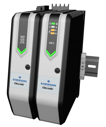
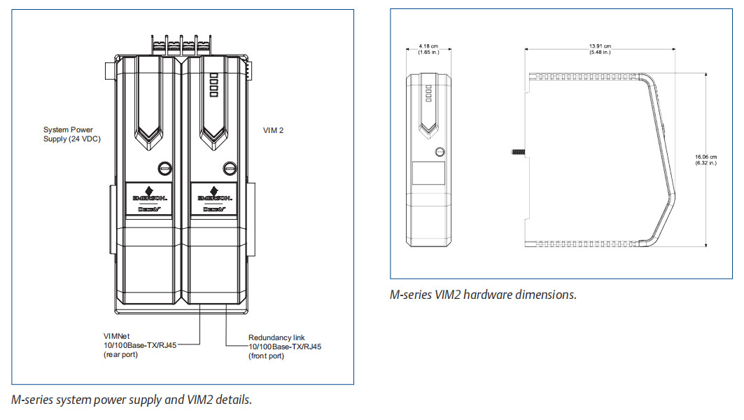
M-series system power supply and VIM2.
Product Description
The VIM2 may be used for either DeltaV I/O simulation or Ethernet I/O device integration. The VIM2 mounts on a 2-wide horizontal or 4-wide vertical carrier on either side of the DeltaV
controller. A dedicated DeltaV system power supply is required.
IO Simulation. When used with Emerson’s Mimic Simulation Software, the VIM2 supports I/O simulation all DeltaV M-series
I/O cards including classic IO, Foundation Fieldbus, ProfibusDP, DeviceNet, ASi-bus and Serial.
Mimic Simulation Software provide dynamic simulation for DeltaV system software acceptance testing and operator training. Mimic works by simulating the DeltaV I/O. It also simulates field devices using Foundation Fieldbus, ProfibusDP, DeviceNet and AS-i buses. In order for Mimic to do this, the real I/O cards are disconnected from the control system. The Mimic driver writes to the I/O subsystem of the DeltaV controller. Process models in Mimic simulate realistic process reactions to control system output signals.
Each process controller being simulated uses one Mimic Simulation Node. The I/O simulation driver is provided with the VIM2 hardware, pre-loaded in the VIM2. Mimic Simulation Software must be purchased separately. Technical support for Mimic Simulation Software and I/O simulation driver is available.
Ethernet I/O Integration. When used with the Ethernet I/O drivers, the VIM2 can communicate with high- speed Ethernet networks over Modbus TCP or EtherNet/IP. Depending on which
Ethernet I/O driver is used to configure the VIM2, the DeltaV controller auto-senses a commissioned VIM2 as four or eight DeltaV I/O Cards.
• In simplex installations these cards will be sensed in slots 57-60 or 61-64.
• In dual simplex installations these cards will be sensed in slots 57 to 64.
• In redundant installations the redundant pairs will be sensed in slots 57 to 64.
Configuration of the I/O signals from the commissioned VIM2 is done in the DeltaV Explorer in the same manner as either for a DeltaV Serial or DeviceNet Card.
VIMNet Explorer. The VIMNet Explorer utility allows the user to commission the VIM2, setup primary, secondary and/ or redundant VIM2s, and the Ethernet I/O network. The user is able to specify the IP address, Subnet Mask, and Gateway of each VIM2 and set the node address and names of each Ethernet I/O device that is used by the VIM2. The VIMNet Explorer is also used to flash upgrade a VIM from one version of a driver to another or to replace an existing driver type with another. Only one Ethernet I/O driver may be loaded in the
VIM2 at one time.The VIMNet Explorer application must run on a workstation that has network connectivity to the Ethernet I/O network. This may be a DeltaV workstation with the 3rd network interface card (NIC) connected to the Ethernet I/O network or may be a non-DeltaV workstation. Connection to the VIM2 is done through the RJ-45 Network Connection on the bottom of the VIM2.
The VIMNet Explorer software installation file for the VIM2 is available on a DeltaV v12 and later workstation and on the DeltaV v12 and later software installation DVD. The VIMNet Explorer software installation file is also provided with the purchase of the Ethernet I/O driver.
VIM2 dual simplex or Redundant setups. Two VIM2s can either be setup as a dual simplex or redundant pair for installations that either consists of a lot of slaves or requires
backup Ethernet I/O networks. Each VIM2 will be installed on its own 2-wide carrier, with its own system power supply to the left side of simplex or redundant DeltaV Controllers.If they are setup for dual simplex operation, both VIM2s will work as Standalone units, therefore no need for the redundancy link cable.
If they are setup for redundant operation, the active and standby VIM2s monitor each other with a continuous status command using the redundancy link cable supplied with
each redundant pair. The active VIM2 communicates over the network to the Industrial Ethernet device and the standby sends an intermittent signal to the device to maintain communication integrity.
The Ethernet I/O drivers are not provided with the VIM2 hardware; they must be purchased separately.
Technical support for the Ethernet I/O drivers is available.
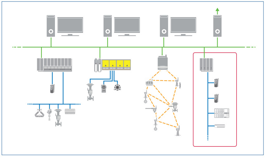
The DeltaV system with M-series VIM2 and Ethernet I/O integration (simplex VIM2 and DeltaV controller shown).
Supported Industrial
Ethernet Protocols
Modbus TCP. The VIM2 with the Modbus TCP Master Driver supports the following Modbus communications protocol function codes to read and write values to and from a Modbus
slave device, as specified by the Modbus Application Protocol
Specification from Modbus-IDA.org.
The VIM2 Modbus TCP/IP Driver supports the following Modbus
function codes:
• Code 1 - Read Coil Status
• Code 2 - Read Input Status
• Code 3 - Read Holding Registers
• Code 4 - Read Input Registers
• Code 5 - Force Single Coil
• Code 6 - Preset Single Register
• Code 8 - Diagnostic Loop Back Test
• Code 15 - Force Multiple Coils
• Code 16 - Preset Multiple Registers
The VIM2 can function as both a Modbus TCP master and slave simultaneously. Master or slave mode is set at the virtual port level. In master-only mode, this driver can communicate with a maximum of 96 slave devices in a simplex and with 192 slave devices in dual simplex setups. Systems that use both master and slave mode can communicate with a maximum of 32 slaves and 32 masters at the same time. The master and slave capability is available in simplex implementations only. In redundant applications, only master mode is supported.
EtherNet/IP. The VIM2 with the EtherNet/IP Scanner Driver provides the following compatible functions using the Common Industrial Protocol (CIP) as defined in the EtherNet/IP Specification from Open DeviceNet Vendor Association and
ControlNet International.
The VIM2 EtherNet/IP Scanner Driver provides:
• IO Adapter (Transport Class 1 target, using connected implicit messaging)
• Unconnected explicit (UCMM) messaging client- Embedded DF1 (PCCC)
• Embedded DF1 is supported in simplex, dual simplex, and redundant configurations. IO Adapter messaging is supported only in simplex and dual simplex configurations.
This driver can communicate with a maximum of 32 slave devices in a simplex and with 64 slave devices in dual simplex setups. In redundant applications, only 16 slave devices are supported.
FMC722 Subsea. The VIM2 with the FMC722 Driver supports communications with FMC Technologies Topside Processing Unit (TPU) using the FMC722 (TPC) protocol.
A maximum of 32/64 slave devices is supported with the FMC722 Subsea driver.ODVA EtherNet/IP. The VIM2 with the ODVA EtherNet/IP Scanner Driver provides the following compatible functions using the Common Industrial Protocol (CIP) as defined in the EtherNet/IP Specification from Open DeviceNet Vendor
Association and ControlNet International. The driver can emulate Programmable Serial cards or DeviceNet cards on the DeltaV I/O Bus.
The VIM2 ODVA EtherNet/IP Driver provides:
• I/O Scanner (Transport Class 1 originator, using connected implicit messaging)
• I/O Adapter (Transport Class 1 target, using connected implicit messaging)
• Unconnected explicit (UCMM) messaging client
• Connected explicit (Transport Class 3 originator) messaging client
This driver can communicate in a simplex, dual simplex, or redundant setup. All configurations support 128 network devices maximum.
PROFINET. The VIM2 with the PROFINET Driver acts as an I/O Controller in a PROFINET network, exchanging data with I/O Devices using Real-Time (RT) messaging. Isochronous real- time (IRT) communication is not supported. It supports the PROFINET v2.2 specification.Field device communications comprise I/O data, alarms and diagnostics. Other aspects of field data, e.g. data records and logbook information, are not supported. Alarm and diagnostic information is reported to PC based VIMNet Explorer tools. Only I/O data and corresponding status are reported to the DeltaV controller.
DeltaV Licensing Guidelines
DeltaV Software Licensing Requirements (DST count) will be used with the ODVA EtherNet/IP driver when DeviceNet Card based Data mapping is selected as for any other v12 and later DeviceNet device. The number of DSTs per connected DeviceNet device will be 1 DST in most cases. The DST type counted will be the most valuable type used to reference a signal for each device. If references are made to more than 16 signals from a device, additional signal references beyond the 16th reference will each count as a DST. A motor starter, for example, with 4 to 5 signal references, will consume 1 DST (typical an AI or DO DST). A remote I/O island will consume 1 DST for the first 16 signal references, and 1 DST for each additional signal reference beyond the 16th signal reference.
For DeltaV versions prior to v12, each signal referenced from a connected Ethernet device will count as 1 DST each.Using all other drivers and options, the DST count will be
impacted by DeltaV Module configuration by using registers, in the same way as Serial Card registers. The following guidelines can be applied:
• A DeltaV Serial Card data set can contain up to 100 values (a value can be any Boolean, 8-bit or 16-bit number), and up to16 data sets are supported by each of the 2 ports on the serial card. If the data set registers are configured as floating point or 32-bit values, then the maximum value is 50. However, the serial device, in general, limits the total capacity of the interface.
• Each data set counts as one DST as long as a single module references all values in the data set. If multiple modules reference values in a data set, then the DST count for the data set is equal to the number of modules referencing the data set.
• Values used in modules containing control function blocks will be counted as Control DSTs.
• Values referenced only in graphics or a history collection count as SCADA values, not DSTs.
Hardware Specifications
|
Specifications for the M-series Virtual I/O Module 2 |
|
|
Power Requirement |
Supplied by System Power Supply, either through the 4-wide vertical (only for simplex setups) or the 2-wide horizontal Power/Controller Carrier. |
|
Maximum Current |
1.4A at 5V DC |
|
Fuse Protection (Internal) |
3.0 A, non-replaceable fuses |
|
Power Dissipation |
5.0 W typical, 7.0 W maximum |
|
User Memory |
48 MB |
|
Mounting |
On right slot of power/controller carrier OR vertical carrier |
|
Size Dimensions |
4.1 cm w x 15.9 cm h x 10.7 cm d |
|
Environmental specifications: |
|
|
Operating Temperature* |
-40° to 60°C (-40° to 140°F) |
|
Storage Temperature |
-40° to 85° C (-40° to 185°F) |
|
Relative Humidity |
5 to 95%, non-condensing |
|
Airborne Contaminants |
ISA-S71.04-1985 Airborne Contaminants Class G3 Conformal coating |
|
Shock (Normal Operating Conditions) |
10 g ½-sine wave for 11 ms |
|
Vibration (Operative Limit) |
1 mm peak-to-peak from 5 Hz to 16 Hz, 0.5 g from 16 Hz to 150 Hz |
|
LED Indicators – On Status: |
|
|
Green – Power |
Indicates DC power is applied. |
|
Red – Error |
Indicates an error condition. |
|
Green – Active |
Indicates that the VIM2 is commissioned and active. |
|
Green – Standby |
Indicates that the VIM2 is redundant and is in standby mode. |
|
Yellow – Network |
Solid - Indicates valid network communication. |
|
Yellow – Ctlr IO |
Indicates valid DeltaV I/O Bus communication. |
|
All except Power flashing, alternating even and odd |
Visual ID of controller initiated from user interface software by ping command. |
|
External connections: |
|
|
Plant Ethernet Network |
Two 100BaseTX RJ-45 connectors (simplex mode only) |
|
Plant Ethernet Network and Redundancy Link |
One 100BaseTX RJ-45 connector (redundant mode) One 100BaseTX RJ-45 connector (cable supplied with redundant modules) |
*Operating any electronics at the higher end of its temperature range for long periods of time will shorten its expected lifetime, see Effects of Heat and Airflow Inside an Enclosure White Paper for more information.
Software Specifications
|
Ethernet I/O Capacity: |
|
|
Max VIM2 per DeltaV Controller |
2 |
|
Max. emulated DeltaV Cards |
4 simplex in simplex setup 8 simplex in dual simplex setup 4 redundant in redundant setup |
|
Amount of Slaves for Serial Data Drivers: |
|
|
EtherNet/IP |
32 in simplex setup / 64 in dual simplex setup 16 in redundant setup |
|
Modbus TCP |
96 in simplex setup / 192 in dual simplex setup 32 in redundant setup |
|
FMC722 Subsea |
32 in simplex setup / 64 in dual simplex setup |
|
ODVA EtherNet/IP |
128 in simplex setup / 256 in dual simplex setup |
|
Amount of Slaves for Bus Card Drivers: |
|
|
ODVA EtherNet/IP |
128 in simplex setup / 256 in dual simplex setup |
|
PROFINET |
128 in simplex setup / 256 in dual simplex setup |
|
Max. Data Sets for Serial Data Drivers: |
|
|
Modbus TCP, EtherNet/IP |
128 in simplex setup / 256 in dual simplex setup 128 in redundant setup |
|
FMC722 Subsea |
128 in simplex setup / 256 in dual simplex setup |
|
ODVA EtherNet/IP |
128 in simplex setup / 256 in dual simplex setup |
|
Max. Data for Bus Card Drivers: |
|
|
ODVA EtherNet/IP |
DeviceNet Card max limits |
|
PROFINET |
PROFIBUS DP Card max limits |
Certifications
The following certifications are available for M-series Virtual I/O Module 2:
• CE:
EMC-EN 61326-1
• FM:
FM 3600
FM 3611
• CSA:
CSA C22.2 No. 213-M1987
CSA C22.2 No. 1010.1
• ATEX: EN60079-0 EN60079-7
• IEC-Ex: IEC60079-0 IEC60079-7
• Marine Certifications: IACS E10
ABS Certificate of Design Assessment. DNV-GL Marine Certificate.
Hazardous Area/Location
M-series Virtual I/O Module 2 can be installed and used based on the following Standards (see actual certificates for exact product markings for each product):
• FM (USA):
Class I, Division 2, Groups A, B, C, D, T4
• cFM (Canada):
Class I, Division 2, Groups A, B, C, D, T4
• ATEX:
II 3G Ex ec IIC T4 Gc
• IEC-Ex:
II 3G Ex ec IIC T4 Gc
Regarding the Installation instructions please refer to the following Documents: Class 1 Division 2 Installation Instructions DeltaV M-series 12P1293 and Zone 2 Installation Instructions DeltaV M-series 12P2046.
产品留言


 with IS CHARMS")

