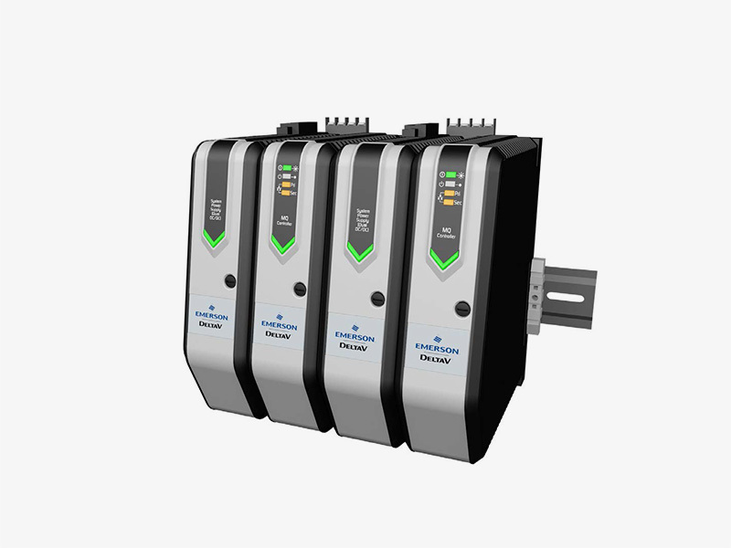
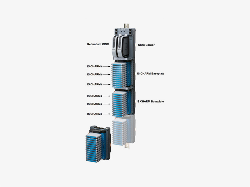
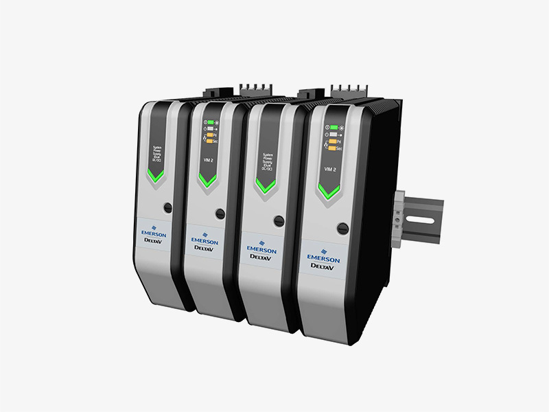
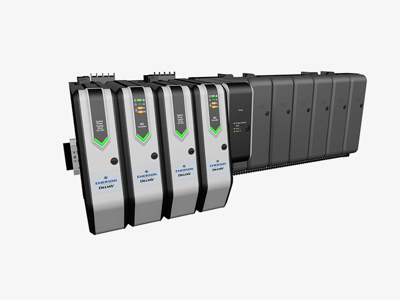
DeltaV SIS™ Safety Network Components
The local safety network (LSN) is the communication backbone of the DeltaV SIS™ process safety system. The LSN is a standard
分类:
Emerson
关键词:

咨询热线:
产品描述
Introduction
The local safety network (LSN) is the communication backbone of the DeltaV SIS™ process safety system. The LSN is a standard
Ethernet network dedicated to the DeltaV SIS system that enables communication between CHARMs smart logic solvers (CSLS) and a single SZ controller. The CSLSs communicate secure parameters and input data to other CSLSs over the LSN.
SZ controllers connect to both the area control network and the LSN to isolate the CSLSs from the process control system.
Starting with v13 and later, the global safety network (GSN) enable safety-rated communication among LSNs while allowing functional segregation on different LSNs. A typical example
is separation of fire and gas (F&G) and emergency shutdown (ESD) applications over separate LSNs while allowing safe and secure communication across both applications. Starting with v14.3.1, the GSN can be logically separated in domains which are a group of LSNs.
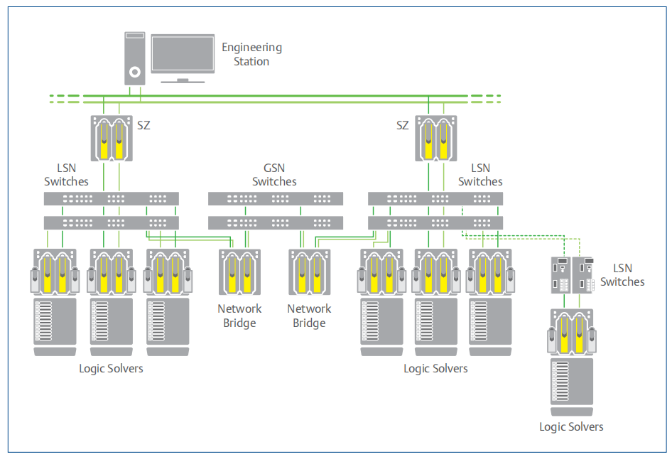
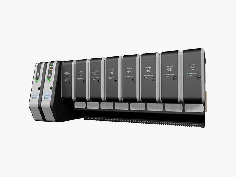
DeltaV SIS safety network architecture diagram.
Benefits
Dedicated to safety. Some systems from other vendors use the same networks for both control and safety. The DeltaV SIS LSN and GSN are dedicated to safety, carrying only safety-rated signals and isolated from the control network. They are therefore immune to any failure of the control network.
Fifty millisecond update time. All the data broadcast on the LSN is available to every CSLS on the same LSN every
50 milliseconds. Combined with the speed of the CSLS, the 50 millisecond update time guarantees input-to-output time of less than 300 milliseconds anywhere on the LSN when the CSLS is configured for 50-millisecond scan rate.
Plug-and-play components. As a dedicated safety network with predictable communications traffic, Emerson has done all of the system testing so you only have to plug the components together to createthe safety networks.
Standards compliance. Network components are compliant with standards such as IEEE, CE, and CSA.
Network diagnostics. The Light Emitting Diodes (LED) on each switch provide health status information. Scalable in small increments. You can expand the system readily and economically by adding hardware incrementally to your system. Just plug another CSLS into the LSN and it is recognized by the system. Online addition of new CSLSs will not interrupt your process.
Fully redundant communications. The safety networks are fully redundant communication networks. The carriers for all nodes have redundant safety network ports for communication with primary and secondary network connections.
DeltaV SIS Smart Switch Specifications
|
Ambient Conditions |
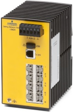
SS6041F01C1 SS6041F05C1 SS6041F06C1 DIN Rail Mount |
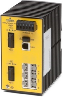
SS6041F01C2 SS6041F05C2 SS6041F06C2 DIN Rail Mount |
SS6048R2P(1-4) Rack Mount Switches |
|
Operating Temperature |
0° to +60°C |
-40° to +70°C |
0° to +50°C |
|
Storage/Transport Temperature |
-40° to +70°C |
-40° to +70°C |
-20° to +85°C |
|
Relative Humidity (Non-Condensing) |
10% to 95% |
10% to 95% |
10% to 95% |
|
Conformal-Coated |
No |
Yes |
No |
|
Harsh Area Rating |
G2 |
G2 (conformal coating allows switch to be used in G3 environments but switch is not certified to G3) |
G2 |
|
Mechanical stability – All switches: IEC 60068-2-27 shock 15 g, 11 ms duration, 18 shocks IEC 60068-2-6 vibration 1 mm, 2 Hz - 13.2 Hz, 90 min.; 0.7g, 13,2 Hz - 100 Hz, 90 min.; 3.5 mm, 3 Hz - 9Hz, 10 cycles, 1 octave/min.; 1g, 9 Hz - 150 Hz, 10 cycles, 1 octave/min. |
|||
|
EMC emitted immunity: FCC CFR47 Part 15 FCC CFR47 Part 15 EN 55022 EN 55022 Class A |
|||
|
EMC interference immunity SS6041F0(1,5,6) DIN rail switches: EN 61000-4-2 electrostatic discharge (ESD) 6 kV contact discharge, 8kV air discharge EN 61000-4-3 electromagnetic field 10 V/m (80 - 1000 MHz) EN 61000-4-4 fast transients (burst) 2 kV power line, 1 kV data line EN 61000-4-5 surge voltage power line: 2kV (line/earth), 1kV (line/line), 1kV data line EN 61000-4-6 conducted immunity 3 V (10 kHz - 150 kHz), 10 V (150 kHz - 80 MHz) |
|||
|
EMC interference immunity: SS6048R2P(1-4) Rack mount switches: EN 61000-4-2 electrostatic discharge (ESD) 4 kV contact discharge, 8kV air discharge EN 61000-4-3 electromagnetic field 10 V/m (80 - 2700 MHz) EN 61000-4-4 fast transients (burst) 2 kV power line, 4 kV data line EN 61000-4-5 surge voltage power line: 2kV (line/earth), 1kV (line/line), 4kV data line EN 61000-4-6 conducted immunity 10 V (150 kHz - 80 MHz) |
|||
|
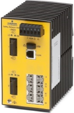
General Specifications for the SS6041F01, SS6041F05, and SS6041F06 DeltaV SIS Smart Switches |
|||
|
Power requirements: Operating voltage: 24 V DC (18-30) V Mechanical construction: Dimensions MM (W x H x D) 74 x 131 x 111 (2.9 x 5.16 x 4.37 in ) Mounting DIN Rail Weight 410 g (14.48 oz) (All models) Protection class IP20 Provided in SS# - qty 1 LSN20 switch with terminal block. |
|
|
|
|
PRODUCT NOTE: These switches are described as supporting local ports and uplink ports. Local ports are connected to a single device such as a SZ Controller or CSLS. An uplink port is connected to another switch. There is no difference in the way the ports function, and a port designated as an “uplink port” can be used as a local port. |
|||
|
General Specifications for the SS6048R2P(1-4) DeltaV SIS Smart Switches |
|
|
Up to 26 port Fast Ethernet/Gigabit Ethernet Industrial Workgroup Switch. |
|
|
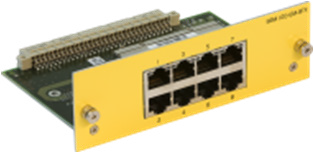
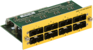
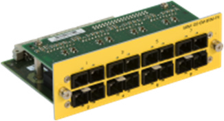
Ports available: Base module has 10 ports -- 2 uplink ports (10/100/1000 wired or using VE6050 SFP modules) and 8 TX ports (10/100 Base-TX) in a fixed configuration. Up to 16 additional 100Mb ports using the SS6049 - 8 port Media Modules in any combination – TX, MM fiber, SM fiber, or 100Mb SFP transceivers. |
|
|
Power supply/signaling contact: 1 x plug-in terminal block, 2-pin, output manual or automatic switchable (max. 1 A, 24 V DC respectively 24 V AC) V.24 interface: 1 x RJ11 socket, serial interface for troubleshooting USB interface: For flash upgrade of switch software Network size - length of cable – base module: Twisted pair (TP)- 8 TX port base module and wired 10/100/1000 ports: 0 – 100m SFP module ports: Supports any combination of VE6050 1Gb or 100FX Transceivers Smart Switch “Stacking” Support: SS6048 switches do not support “stacking”. To create a central switch(s) of greater than 24 ports switches should be interconnected using the front panel gigabit ports Power requirements: Operating voltage 100 - 240 VAC, 47 - 63 Hz Rated Current 0.4 – 0.2 A Power output in Btu (IT) h –41 (without media modules) Power consumption 12 W (without media modules) Mechanical construction: Dimensions 448 x 310 x 44 (without mounting bracket) Mounting 19" control cabinet Weight 3.60 kg Protection class IP20 Provided SS60 device, terminal block for signal contact, 2 brackets with fastening screws (pre-assembled), and housing feet - stick-on, power cable. Order separately: Expansion modules, Fast Ethernet SFP modules, Gigabit Ethernet SFP modules. Expansion modules SS6049M01, SS6049M02, SS6049M03, and SS6049M04 can be used with SS6048-series DeltaV SIS Smart switches. When rail mounted these switches require additional mounting supports in addition to 19” rail mounting brackets |
|
|
Specifications for SS6049 Expansion Modules |
||||
|
|
|
|
|
|
|
|
Specifications for SS6049M01 |
Specifications for SS6049M02 |
Specifications for SS6049M03 |
Specifications for SS6049M04 |
|
Length of cable |
100m |
See fiber cable specs |
See fiber cable specs |
See fiber cable specs |
|
Power requirements: Current consumption Power output in Btu(IT) h |
2 W 7 |
10 W 7 |
10 W 7 |
11 W 7 including SFP modules |
|
Mechanical constructions: Dimensions MM (W x H x D) Weight Protection class |
138 x 90 x 42 0.21 Kg IP 20 |
138 x 90 x 42 0.18 Kg IP 20 |
138 x 90 x 42 0 .18 Kg IP 20 |
138 x 90 x 42 0 .13 Kg IP 20 |
Fiberoptic Cable Specifications – Apply to All DeltaV SIS Smart Switch Models
|
Fiberoptic Cable Types |
Specifications Specifications apply to all fiber connections on any model of DeltaV SIS Smart Switches Actual fiberoptic distances achieved depend on the fiber type used and other components installed on the network such as splices and patch panels that can reduce Fiberoptic signal strength. |
|
Multimode fiber (MM) 50/125 μm |
0 - 5000 m, 8 dB link budget at 1300 nm, A = 1 d/km, 3 dB reserve, B = 800 MHz x km |
|
Multimode fiber (MM) 62.5/125 μm |
0 - 4000 m, 11 dB link budget at 1300 nm, A = 1 dB/km, 3 dB reserve, B = 500MHz x km |
|
Single mode fiber (SM) 9/125 μm |
0 – 32.5 km, 16 dB link budget at 1300 nm, A = 0,4 dB/km, 3 dB reserve, D = 3,5ps/(nm x km) |
|
Single mode fiber (LH) 9/125 μm (long haul transceiver): |
24 – 86.6 km, 7 - 29 dB link budget at 1550 nm, A = 0,3 dB/km, 3 dB reserve, D = 19 ps/(nm x km) |
DeltaV SIS Smart Switch Certifications
|
Declaration/ Approval |
LSN20 SS6041 |
LSN20-ES SS6041 |
SRM100 SS6048 |
|
CE Declaration – Basic Standards EMC (Harmonized European Standards according to EMC-Directive 2004/108/EC • EN 55022 Emission of ITE • IEC/EN 61000-6-2:2005 – Immunity in industrial environment • EN 61000-3-2:2000 + A2:2005 – Limits for harmonic current emissions • EN 61000-3-3:1995 + A1:2001 – Limitation of voltage changes, voltage fluctuations and flicker Safety (Harmonized European Standards according to Low-Voltage- Directive 2006/95/EG) • EN 61131-2:2003 – Programmable Controllers |
Class A |
Class A |
Class A |
|
FCC Declaration - CFR47: 2005, Part 15 |
Class A |
Class A |
Class A |
|
cUL Approval according to UL 508 • UL 508:2003 – Industrial control equipment – US. Safety standard • CSA 22.2 No. 142-M1997 – Industrial control equipment – Canadian safety standard |
Yes |
Yes |
Yes |
|
cUL Approval according to ISA-12.12.-01 Class 1 Div. 2 /UL1604 • ANSI/ISA 12.12.01:2000, Approved 2001 • CSA 22.2 No. 213-M1987 |
Yes |
Yes |
N/A |
|
IEC/EN 61131-2 Declaration - EN 61131-2 : 2003 – Programmable Controllers |
Yes |
Yes |
N/A |
|
cUL Approval according to UL 60950-1 • UL 60950-1:2003 – Safety of Information Technology Equipment – US. Safety standard • CSA 22.2 No. 950:1998 – Safety of Information Technology Equipment – Canadian safety standard |
N/A |
N/A |
Yes |
|
IEC/EN 60950-1 Certification according to CB-scheme • EN 60950-1:2003 – Information technology equipment – Safety |
N/A |
N/A |
Yes |
|
ATEX 100a Approval, Zone 2, • according to EN 60079-15:2005 – Electrical apparatus for explosive atmospheres |
N/A |
Yes |
N/A |
|
DNV-GL |
No |
Yes |
No |
|
RCM (Australia) |
Yes |
Yes |
Yes |
|
EAC (Russia): pending |
Yes |
Yes |
Yes |
|
EAC Ex (Russia): pending |
N/A |
Yes |
N/A |
In order to comply with the EN 60950-1 standard (paragraph 4.3.15.5) the DeltaV SIS Smart Switches containing laser diode must also comply with the Accessible Emissions Limit
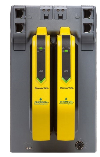
LSNB
Beginning with DeltaV v13, a LSNB can be installed on two or more LSNs, so multiple LSNs may be connected over a GSN.
DeltaV SIS Smart Switches require no configuration to function on the safety networks. However, to support GSN functionality the DeltaV SIS Smart Switch must have software v4.2.14 or later.
DeltaV SIS Smart Switches are the only supported switches to be used within the LSN and GSN.
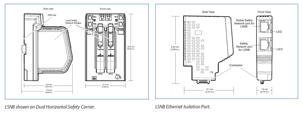
LSNB Specifications
Hardware
|
Specifications for Dual Horizontal Safety Carrier |
|
|
Capacity |
Redundant LSNBs |
|
Input power |
+24 V DC ±10% at 1 A maximum |
|
Battery power |
+5.0 to +12.6 V DC at 30 uA typical |
|
Redundant Ethernet connections through replaceable Ethernet Isolation Ports (EIPs) |
Copper twisted pair: 10/100BASE-TX with RJ45 connectors; Full duplex operation - 100 m distance |
|
Mounting |
DIN rail latch to horizontally orientated T-type rail |
|
Specifications for LSNB |
|
|
Number of GSNs per system |
One GSN per system. Up to 16 LSNBs per domain can publish information to the GSN. There is no limit for the number of LSNBs subscribing to information from the GSN. |
|
Input power |
+24 V DC ± 10% at 575 mA maximum for redundant |
|
Heat dissipation (redundant) |
13 Watts maximum for redundant |
|
Mounting |
Slots on the Dual Horizontal Safety Carrier |
|
Communication |
Redundant Ethernet connections through Dual Horizontal Safety Carrier to the: • LSN • GSN |
|
LED Indicators |
|
|
Green – Power |
Indicates DC power is applied. |
|
Red – Error |
Indicates an error condition or unassigned LSNB. |
|
Green – Active/Standby |
Indicates operating mode of each LSNB. |
LSNB Certifications
The following certifications are available for the LSNB:
• CE:
EMC- EN 61326-1
• FM:
FM 3600
FM 3611
FM 3810
• CSA:
CSA C22.2 No. 213-M1987 CSA C22.2 No. 1010-1
• ATEX:
ATEX 94/9/EC EN60079-0 EN60079-15
• IEC-Ex: EN60079-0 EN60079-15
• Marine Certifications:
IACS E10
• ABS Certificate of Design Assessment
• DNV-GL Marine Certificate
Hazardous Area/Location:
The LSNB can be installed and used based on the following Standards:
• FM (USA):
Class I, Division 2, Groups A, B, C, D, T4
• cFM (Canada):
Class I, Division 2, Groups A, B, C, D, T4
• ATEX:
Ex nA IIC T4 Gc
• IEC-Ex:
Ex nA IIC T4 Gc
产品留言


